261 Results
View results:
Sort by:

In this article, a lap joint of a ZL purlin on a monopitch roof is modeled and designed using the Steel Joints add-on, and compared with the load-bearing capacity table of the manufacturer.

Both the determination of natural vibrations and the response spectrum analysis are always performed on a linear system. If nonlinearities exist in the system, they are linearized and thus not taken into account. They are caused by, for example, tension members, nonlinear supports, or nonlinear hinges. This article shows how you can handle them in a dynamic analysis.

With the Steel Design add-on, you can design structural steel components in the event of fire using the simple design methods according to Eurocode 3. The component temperature at the time of the design check can be determined automatically according to the temperature-time curves specified in the standard. In addition to considering a cladding for fire protection, it is also possible for you to take account of the beneficial properties of hot-dip galvanization.

The dynamic analysis in RFEM 6 and RSTAB 9 is divided into several add-ons. The Modal Analysis add-on is a prerequisite for all other dynamic add-ons, since it performs the natural vibration analysis for member, surface, and solid models.

Modal analysis is the starting point for the dynamic analysis of structural systems. You can use it to determine natural vibration values such as natural frequencies, mode shapes, modal masses, and effective modal mass factors. This outcome can be used for vibration design, and it can be used for further dynamic analyses (for example, loading by a response spectrum).

The quality of the structural analysis of buildings is significantly improved when the soil conditions are considered as realistically as possible. In RFEM 6, you can realistically determine the soil body to be analyzed with the help of the Geotechnical Analysis add-on. This add-on can be activated in the model’s Base Data as shown in Image 01.

Seismic Analysis in RFEM 6 is possible using the modal analysis and the response spectrum analysis add-ons. As a matter of fact, the general concept of the earthquake analysis in RFEM 6 is based on the creation of a load case for the modal analysis and the response spectrum analysis, respectively. The standard groups for these analyses are set in the Standards II tab of the model’s Base Data.

This technical article presents some basics for using the Torsional Warping add-on (7 DOF). It is fully integrated into the main program and allows you to consider the cross-section warping when calculating member elements. In combination with the Stability Analysis and Steel Design add-ons, it is possible to perform the lateral-torsional buckling design with internal forces according to the second-order analysis, taking imperfections into account.

One of the innovations in RFEM 6 is the approach to designing steel connections. In contrast to RFEM 5, where the design of steel joints is based on an analytical solution, the Steel Joints add-on in RFEM 6 offers an FE solution for steel connections.

This article compares the design to the one in the referenced article: Design of Concrete Columns Subjected to Axial Compression with RF-CONCRETE Members. It is, therefore, about taking exactly the same theoretical application carried out in RF-CONCRETE Members and reproducing it in RF-CONCRETE Columns. Thus, the objective is to compare the different input parameters and the results obtained by the two add-on modules for the design of column-like concrete members.

In this article, the adequacy of a 2x4 dimension lumber subject to combined biaxial bending and axial compression is verified using the RF-/TIMBER AWC add-on module. The beam-column properties and loading are based on example E1.8 of AWC Structural Wood Design Examples 2015/2018.

The add-on modules for designing structural member components according to national, European, and international standards also show design results in addition to numerical output in tables graphically, as diagrams displayed on the framework.

Foundations including dimensions can be saved as a template in a user-defined database.

In RFEM 5 as well as RSTAB 8 in RF-/FOUNDATION Pro, you can save the foundation dimensions for all five foundation types as foundation templates in a user-defined database and use them later in other models.

In RF-/FOUNDATION Pro, the foundation design requires the definition of the corresponding loading (load cases, load combinations, or result combinations) for different design situations (STR, GEO, UPL, or EQU).

When modeling structural bearing systems, especially hall structures, some substructures of a foundation with no influence on the rising structure are not modeled in RFEM/RSTAB. In the case of hall structures, these are, for example, reinforced concrete floor slabs, strip foundations, and the ties between column foundations.

A member's boundary conditions decisively influence the elastic critical moment for lateral-torsional buckling Mcr. The program uses a planar model with four degrees of freedom for its determination. The corresponding coefficients kz and kw can be defined individually for standard-compliant cross-sections. This allows you to describe the degrees of freedom available at both member ends due to the support conditions.
In the case of a reinforced concrete model represented as a mixed structure consisting of surface and member elements, the design is carried out in different modules.

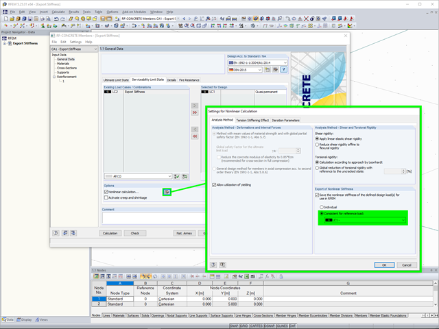
The RF-STABILITY add-on module determines any critical load factors, effective lengths, and eigenvectors of RFEM models. Stability analyses can be carried out by various eigenvalue methods, the advantages of which depend on the structural system as well as computer configurations.

In the RF-/TIMBER Pro, RF-/TIMBER AWC, and RF-/TIMBER CSA add-on modules, you can consider the resulting deformation of a member or set of members. In addition to the local directions y and z, you have the option "R." This allows you to compare the total deflection of a girder to the limit values given in the standards.

Designing vertical insulating glass requires assigning different loads on the individual layers of the entire glass unit. This occurs, for example, with simultaneous actions from wind loads and fall protection.

To work even more efficiently, RF‑GLASS allows you to create and save different, user‑defined layer structures that can be reimported later or loaded in another project.
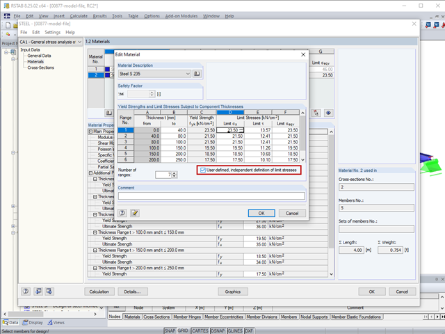
The limit stresses in RF‑/STEEL can be user-defined for each thickness range.
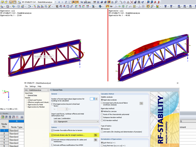
When analyzing structural elements susceptible to buckling by using the modules RF‑STABILITY (for RFEM) or RSBUCK (for RSTAB), it might be necessary to activate the internal division of members.

The RF‑/STEEL EC3 add-on module can perform the design of fillet welds for all parametric, welded cross-sections of the cross-section library. For this, the option must be activated in the detail settings of the module. As an alternative, you can also use a surface model for the design.

In RF‑/FOUNDATION Pro, the available reinforcing steel diameters can be adjusted by the user. The adjustment of the available rebar diameters works similarly to the same function in the RF‑/CONCRETE (Members) and RF‑/CONCRETE Columns add‑on modules.
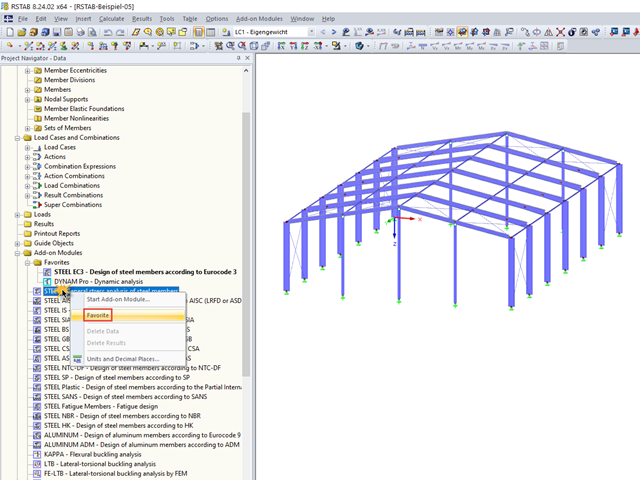
In RFEM and RSTAB, you can create add-on modules as favorites.

Once you have determined the final tendon geometry in RF‑TENDON, exporting the model to a CAD program can be useful. For this purpose, the module includes the option to export the file in the .dxf file format. You can select the export function by right-clicking the workspace. After selecting the DXF format and the storage location, additional settings can be made.

In RF-/FOUNDATION Pro, the user can freely select the proportion of the relieving soil pressure by means of the factor kred.

For designing glass in the RF‑GLASS add‑on module, you can use one of two calculation methods: a 2D or a 3D calculation. The main difference between these design options is the automatic modeling of the layers in a temporary model. In a 2D calculation, each layer is generated as a surface element (plate theory); in a 3D calculation, it is generated as a solid. Depending on the selected layer composition, you can either select an option or find it preselected by the program.